Where it is
📷
Add location photo
Replace this box with your shot of the kick panel — cover off, box visible. File:
assets/location.jpg
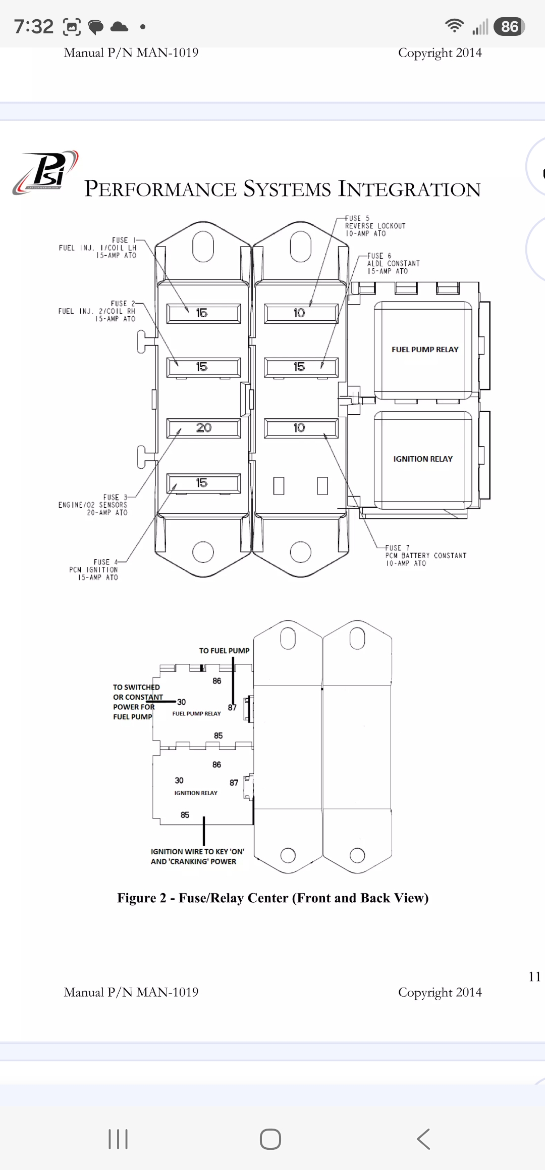
Fuse layout — as it sits in the box
Left column
15A
Fuse 1
Fuel Inj 1 / Coil LH
15A
Fuse 2
Fuel Inj 2 / Coil RH
20A
Fuse 3
Engine / O2 Sensors
15A
Fuse 4
PCM Ignition
Right column
10A
Fuse 5
Reverse Lockout
15A
Fuse 6
ALDL Constant
10A
Fuse 7
PCM Battery Constant
Fuel Pump Relay
Right side of box
Ignition Relay
Key ON + cranking
All fuses are standard ATO/ATC blade type. Amp rating is printed on each fuse — match color if in doubt.
Box reference photo
Harness connection points
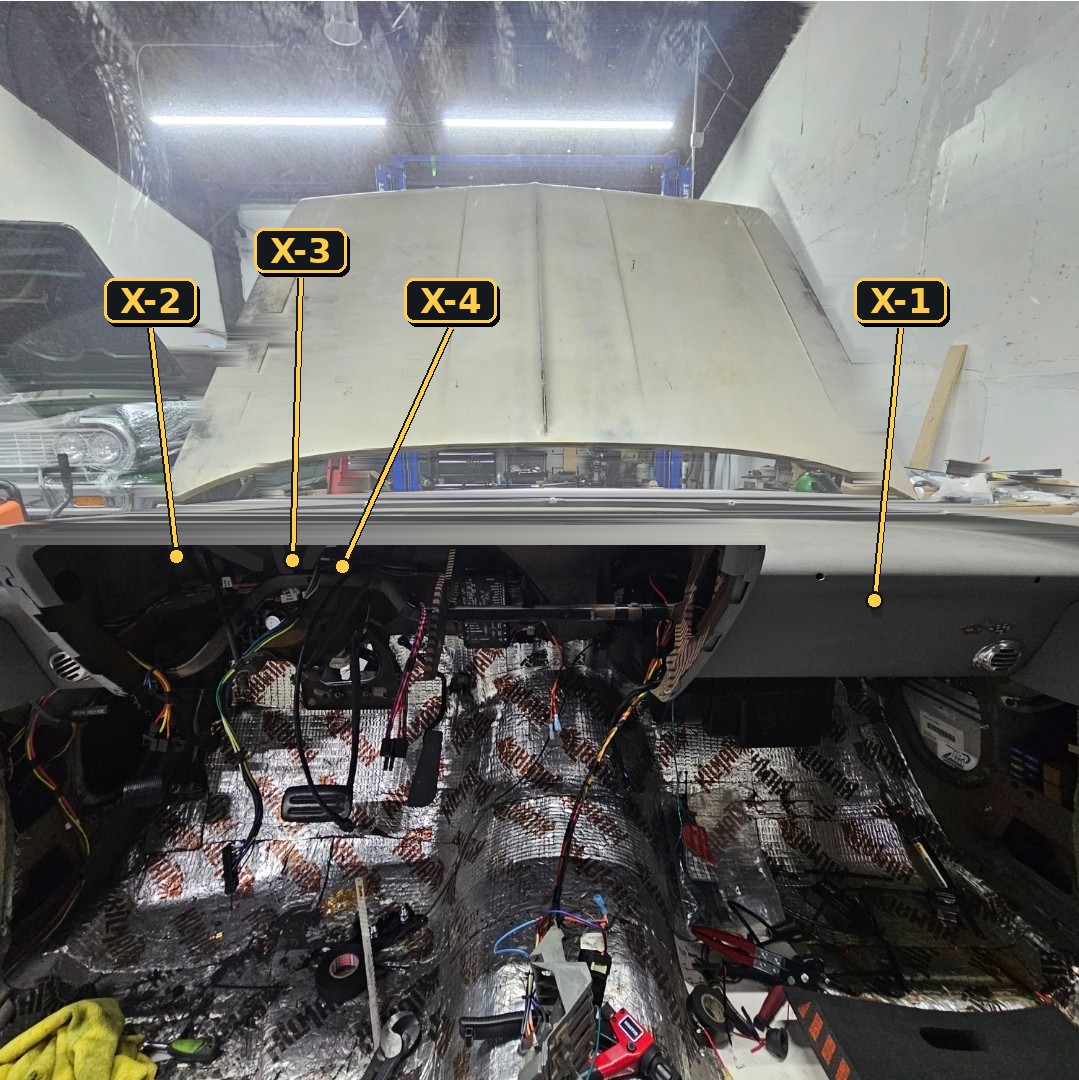
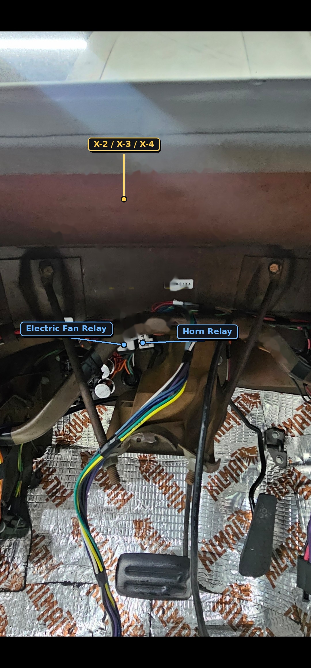
X-1
Under passenger dash
Power / ignition / fuel pump
X-2
Behind cluster
Ignition power to brake switch (VCC)
X-3
Behind cluster
PCM to brake switch
X-4
Behind cluster
Ground from PCM to fan relay
Relay locations
Wiring reference
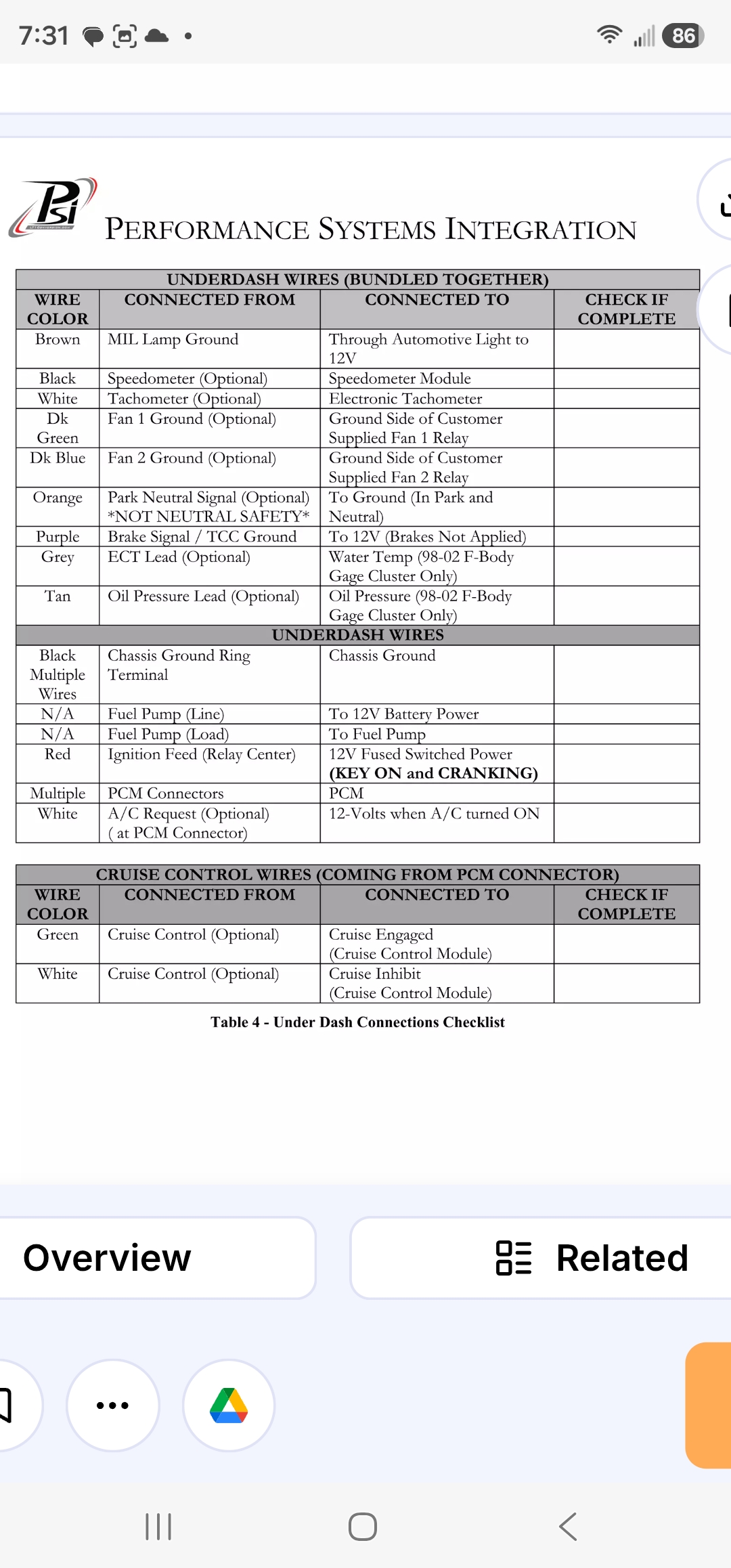
Underdash wire checklist (PSI) ›
Optional and required leads bundled at the PSI harness, with where each one lands.
| Color | From | To |
|---|---|---|
| Brown | MIL lamp ground | Through lamp to 12V |
| Black | Speedometer (opt) | Speedometer module |
| White | Tachometer (opt) | Electronic tach |
| Dk Green | Fan 1 ground (opt) | Ground side, Fan 1 relay |
| Dk Blue | Fan 2 ground (opt) | Ground side, Fan 2 relay |
| Orange | Park neutral signal (opt) NOT neutral safety | To ground in Park & Neutral |
| Purple | Brake signal / TCC ground | To 12V, brakes not applied |
| Grey | ECT lead (opt) | Water temp, 98–02 F-body cluster |
| Tan | Oil pressure lead (opt) | Oil press, 98–02 F-body cluster |
| Red | Ignition feed (relay center) | 12V fused switched — key ON + cranking |
| White | A/C request (opt, at PCM) | 12V when A/C on |
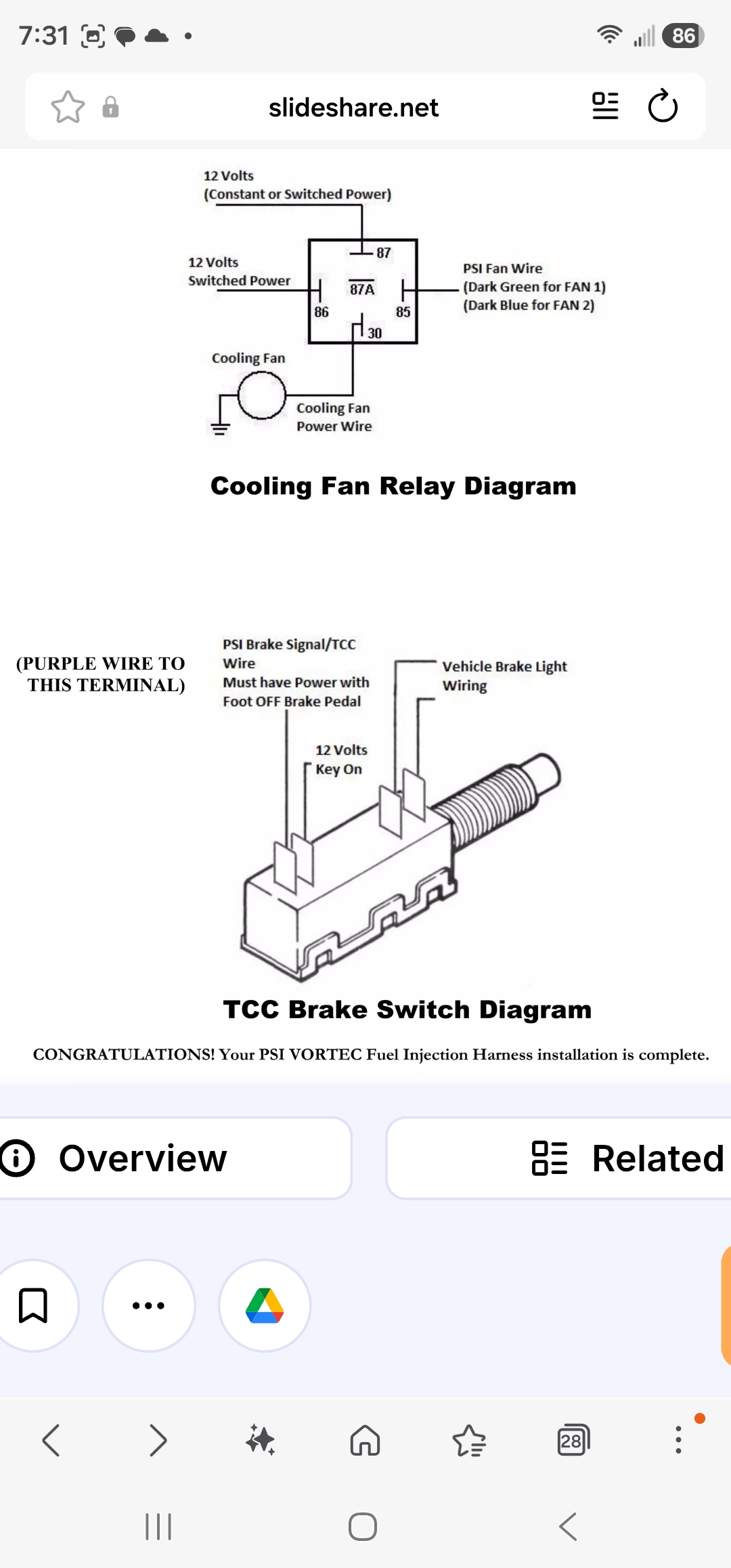
Cooling fan relay & TCC brake switch ›
Fan relay: PSI fan wire triggers terminal 85/86. Dk green = Fan 1, dk blue = Fan 2. Brake switch: purple wire to the terminal with power when foot is OFF the pedal.
Full PSI checklist page (photo) ›